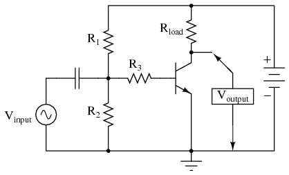
Therefore, if Vinput increases by 100 mV, then VB-E increases by 100 mV: a change in one is the same as a change in the other since the two voltages are equal to each other. In other words, with no feedback resistor, VB-E equals Vinput. With no feedback resistor connecting the emitter to ground in the figure below (a), whatever level of input signal (Vinput) makes it through the coupling capacitor and R1/R2/R3 resistor network will be impressed directly across the base-emitter junction as the transistor’s input voltage (VB-E). Let’s take a closer look at the emitter-base junction and see what difference this new resistor makes in the figure below.

This new feedback resistor drops voltage proportional to the emitter current through the transistor, and it does so in such a way as to oppose the input signal influence on the base-emitter junction of the transistor. The oscilloscope waveforms are shown in the figure below.Ĭommon-emitter amplifier, no feedback, with reference waveforms for comparison.īecause the output is inverted, or mirror-image, reproduction of the input signal, any connection between the output (collector) wire and the input (base) wire of the transistor in the figure below will result in negative feedback.Įmitter feedback: A different method of introducing negative feedback into a circuit. In other words, a positive-going input voltage causes the output voltage to decrease, or move toward the negative, and vice versa. Like all common-emitter amplifiers, this one inverts the input signal as it is amplified. We could omit it for maximum voltage gain, but since base resistors like this are common in common-emitter amplifier circuits, we’ll keep it in this schematic. Resistor R3 serves the purpose of controlling voltage gain. The capacitor couples Vinput to the amplifier so that the signal source doesn’t have a DC voltage imposed on it by the R1/R2 divider network. The amplifier configuration shown here is a common-emitter, with a resistor bias network formed by R1and R2. Let’s examine a simple amplifier circuit and see how we might introduce negative feedback into it, starting with the figure below.Ĭommon-emitter amplifier without feedback. However, the advantages of stability, lower distortion, and greater bandwidth are worth the tradeoff in reduced gain for many applications. If a portion of an amplifier’s output signal is “fed back” to the input to oppose any changes in the output, it will require a greater input signal amplitude to drive the amplifier’s output to the same amplitude as before. The tradeoff for these advantages (there just has to be a disadvantage to negative feedback, right?) is decreased gain. While positive feedback drives an amplifier circuit toward a point of instability (oscillations), negative feedback drives it the opposite direction: toward a point of stability.Īn amplifier circuit equipped with some amount of negative feedback is not only more stable, but it distorts the input waveform less and is generally capable of amplifying a wider range of frequencies. On the other hand, Negative feedback has a “dampening” effect on an amplifier: if the output signal happens to increase in magnitude, the feedback signal introduces a decreasing influence into the input of the amplifier, thus opposing the change in the output signal. Oscillators are very useful circuits, and so feedback has a definite, practical application for us. This is one way to make an oscillator circuit to produce AC from a DC power supply. One might wonder what possible benefit feedback is to an amplifier circuit, given such an annoying example as PA system “howl.” If we introduce positive, or regenerative, feedback into an amplifier circuit, it tends to create and sustain oscillations, the frequency of which is determined by the values of components handling the feedback signal from output to input. the result being a noise of steadily increasing volume until the system becomes “saturated” and cannot produce any more volume. Specifically, this is an example of positive or regenerative feedback, as any sound detected by the microphone is amplified and turned into a louder sound by the speaker, which is then detected by the microphone again, and so on.


Reinforces the direction of an amplifier’s output voltage change, while negative feedback does just the opposite.Ī familiar example of feedback happens in public-address (“PA”) systems where someone holds the microphone too close to a speaker: a high-pitched “whine” or “howl” ensues, because the audio amplifier system is detecting and amplifying its noise.

If some percentage of an amplifier’s output signal is connected to the input, so that the amplifier amplifies part of its output signal, we have what is known as feedback.įeedback comes in two varieties: positive (also called regenerative ), and negative (also called degenerative ).


 0 kommentar(er)
